Die-to-Die Interface Physical Implementation for UCIe Compliant Designs
The hard physical constraints that make multi-vendor chiplet interoperability actually work.
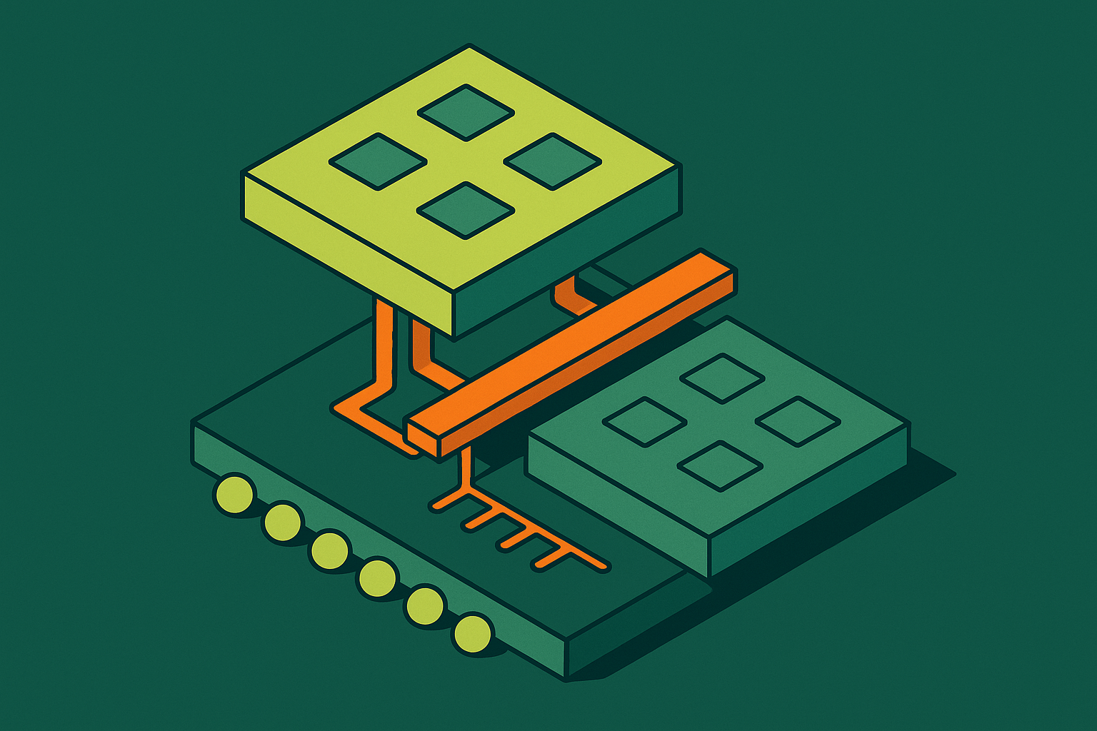
Die shrinks used to mean cost savings. Past a certain node, that math breaks down, since the smaller the geometry, the more a single defect can knock out a chip that took months to design, and the yield curve punishes big monolithic dies hardest. That's the economic pressure behind chiplet disaggregation, and it's why the standard governing chiplet interconnects now sits at the center of physical design decisions that used to be internal to a single team, a single die, a single vendor. Building a UCIe-compliant die-to-die interface means working inside a specific set of physical constraints, bump placement, PHY floorplanning, the FDI and RDI boundaries, package co-design, and locking down those decisions in the right order makes the design tape out clean, while getting the order wrong sends it back from the fab as an expensive lesson.
Before UCIe, chiplet interconnect was a patchwork. AIB from the Chips Alliance, OIF's XSR and USR, OCP's BOW and OpenHBI: each solved die-to-die communication for a particular consortium or use case, but none of them talked to each other. A team building with a Chips Alliance chiplet and a die that only supported an OIF interface had no path to plug the two together. That fragmentation made multi-vendor chiplet assembly a theoretical benefit rather than a practical one, because interoperability wasn't guaranteed by any shared spec, just by whoever happened to share the same in-house interface.
UCIe closed that gap starting in March 2022, when a founding consortium introduced a new shared specification for chiplet interconnects. The founding members, AMD, Arm, ASE Group, Google Cloud, Intel, Meta, Microsoft, Qualcomm, Samsung, and TSMC, represented the full chain from IP design through foundry through OSAT packaging, and that full chain is what a die-to-die standard needs behind it to mean anything. Membership has grown since to roughly 130 companies worldwide. The promise UCIe makes is straightforward to state and hard to deliver: a system designer should be able to mix chiplets from different vendors, built on different process nodes, packaged through any OSAT, and get guaranteed interoperability at the physical and protocol level. That promise is the design constraint. Everything downstream in physical implementation exists to honor it.
How each UCIe spec revision changed physical design
UCIe 1.0 laid the groundwork: the three-layer stack, two PHY variants, and mapping to existing protocols like PCIe and CXL so chiplet interfaces didn't need a whole new software and validation ecosystem built from scratch.
UCIe 1.1 added a streaming protocol mode with error detection and packet replay. It sounds like a small addition, but it was the first revision that actually reached into adapter-layer implementation, since replay logic needs buffering and state tracking that has to live somewhere in the physical design.
UCIe 2.0 is where the floorplan assumptions started to shift for real. It introduced 3D packaging support through the UCIe-3D PHY, with hybrid bonding pitches down into the sub-micron range, and it added the UCIe DFx Architecture (UDA), a standardized approach to testability and debug across a chiplet's life from tapeout through field deployment. Once 3D stacking is on the table, floorplanning is no longer just a shoreline problem: it becomes a volumetric one.
UCIe 3.0, the version most physical design teams are targeting now, pushed data rates to 48 GT/s and 64 GT/s, added runtime recalibration, and extended sideband channel reach out to 100mm. It also brought continuous transmission protocol support, early firmware download standardization, priority sideband packets for low-latency signaling, and fast throttle and emergency shutdown mechanisms, all while keeping full backward compatibility with earlier revisions. For a physical designer, 3.0 changes wire length budgets, timing margins, and how much has to be squeezed into the PHY at higher speed without breaking compatibility with a 1.0-era chiplet sitting on the other side of the link.
The three-layer stack and physical implementation responsibility in each layer
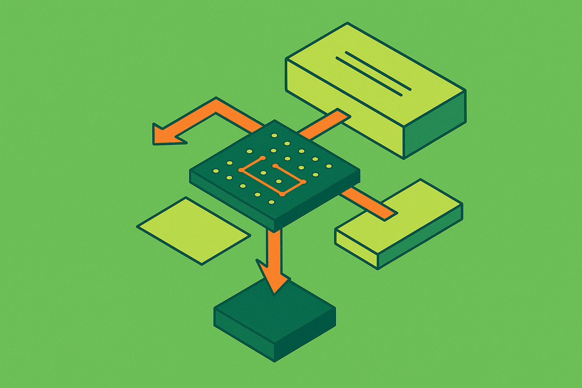
UCIe organizes the interface into three layers, the Physical Layer (PHY), the Die-to-Die Adapter (D2D Adapter), and the Protocol Layer. Each one has its own physical footprint, and more importantly, its own design ownership, which matters enormously once IP starts coming from more than one vendor.
The FDI, or Flit-Aware Die-to-Die Interface, is the standardized boundary between the Protocol Layer and the D2D Adapter. On paper it reads as a logical handshake. In practice, its timing closure requirements reach directly into how the adapter block gets floorplanned, because a boundary that looks clean in RTL can still generate a mess of constrained paths once it's placed.
The RDI, or Raw Die-to-Die Interface, sits between the D2D Adapter and the PHY. This is where bump-map constraints and PHY layout meet adapter logic head-on. Getting RDI timing right isn't a paperwork exercise handled in the RTL sign-off meeting: it's a physical implementation problem, full stop, and treating it as anything less invites a respin.
RDI and FDI may be considered related to, or a subset of, the Logical PHY Interface (LPIF) 2.0 specifications, which matters for teams sourcing IP from multiple vendors. Anyone buying adapter IP from one company and PHY IP from another needs to understand how their vendors' documentation maps onto LPIF 2.0 terms, because a mismatch in interpretation here tends to surface late, during integration, when it's expensive to fix.
PHY variant selection: how Standard and Advanced package types set different physical ground rules from day one
UCIe defines two main PHY variants, and the choice between them sets the physical ground rules before a single bump gets placed.
UCIe-S, the Standard variant, targets bump pitches of 100 to 130 microns on organic substrate or laminate packaging. It's a coarser floorplan by necessity, shaped by the density limits of standard package technology. UCIe-A, the Advanced variant, pushes bump pitch down to 25 to 55 microns and requires a silicon interposer, EMIB, or hybrid bonding to achieve it. That tighter pitch buys a real number: substantially higher bandwidth density than the Standard variant. That's the tradeoff a team is actually making when picking between the two, not an abstract preference but a direct bandwidth-per-millimeter number weighed against packaging cost and complexity.
UCIe-3D, introduced in the 2.0 revision, goes further still. It's built around hybrid bonding, with pitches from 10 to 25 microns down to 1 micron or less. The bigger shift isn't the pitch number, though, it's the geometry: UCIe-3D's hybrid bonding approach changes the geometric assumptions that 2D and 2.5D integration depend on. Interconnect distance approaches zero, which cuts electrical parasitics dramatically. That geometric shift is what changes the signaling assumptions covered next, because a PHY built for shoreline connections doesn't just shrink to fit an areal bump field, it has to be rethought.
PHY floorplanning: bump map constraints, lane topology, and the signaling choices baked into the layout
UCIe uses a forwarded clock architecture: a single differential pair carries the timing reference for a whole cluster of lanes, and every data lane runs single-ended. That's a deliberate tradeoff, trading some signal integrity margin for bandwidth density, since single-ended signaling needs half the bumps per lane that differential signaling would. It also means the PHY floorplan has one job it cannot get wrong: keep that forwarded clock path away from aggressor coupling. If the clock reference picks up noise from a switching data lane next to it, every lane relying on that clock inherits the error.
Two supporting lane types also need explicit bump-map placement. The Valid lane marks which data lane samples are real payload versus idle, and the Track lane supports synchronization. Both need bump locations that are clearly separated, physically, from the high-toggle data lanes around them, since their signal integrity matters just as much as the forwarded clock's.
Inside the PHY boundary, several more blocks need placement, including a PRBS-based scrambler and descrambler for DC balance, the low-speed out-of-band sideband channel, and lane mapping and reversal logic. That last one deserves particular attention. Lane reversal logic matters most exactly when die orientation isn't locked at floorplan time, which is common in multi-die packages where the same die design gets flipped or rotated depending on which position it occupies.
And then there's the extended sideband reach that UCIe 3.0 enables, pushing out to 100mm. At that span, the wire length budget for sideband routing changes meaningfully, and depending on the package, that may force repeaters or buffering directly into the PHY layout that shorter-reach designs never needed.
D2D Adapter layer: its physical function and the importance of its placement relative to the PHY and FDI boundary
The adapter carries real physical weight, not just control logic. Link initialization alone runs through four stages, Reset of Flow, Sideband Initialization, Mainband Training and Repair, and Protocol parameter exchange, and each stage needs state machines and buffering that occupy real silicon. On top of that sits link state management, optional CRC with link-level retry for reliable delivery, and protocol arbitration when more than one protocol shares the same physical link.
The flit, a 256-byte unit, is the underlying transfer unit whenever the adapter provides reliable delivery, and its buffer has to be sized and placed with the same care as any other timing-critical structure. At UCIe 3.0's higher data rates of 48 and 64 GT/s, that flit buffer's physical size and access latency stop being a minor implementation detail and become a real constraint on timing closure.
Protocol mapping adds another wrinkle. PCIe and CXL both map natively onto the UCIe flit format, and the adapter has to arbitrate between them when both are present. The arbitration logic's placement should minimize wire length to the FDI boundary, since that's where the protocol layer hands transactions off, and every extra millimeter of routing there is extra latency and extra risk.
None of that matters, though, if the adapter's output can't meet setup and hold timing at the RDI boundary. The adapter block should sit as close to the PHY as the floorplan allows, and any feedthrough routing between the two, at the fine pitches UCIe-A and UCIe-3D require, is a real signal integrity risk, not a theoretical one.
FDI and RDI as physical boundaries: how to define them in the floorplan so they stay clean across integration
FDI should function as a hard partition line in the floorplan. All protocol-layer logic sits on one side, all adapter logic on the other, and no logic straddles it. That's not a stylistic preference; it's what enforces the vendor-separation guarantee the whole UCIe spec was built around. Blur that line and the interoperability promise stops meaning anything in practice, even if it still holds on paper.
RDI works as the physical handshake between digital adapter logic and the analog PHY. That's the exact point where digital timing constraints, expressed in SDC, transition into analog signal integrity constraints: S-parameters, eye masks, the language of PHY characterization. Implementation teams need a clear, defined handoff between their own digital STA flow and whatever characterization data the PHY vendor supplies, because those two worlds don't speak the same language by default.
This becomes non-negotiable in a multi-vendor sourcing scenario, protocol IP from one company, adapter IP from another, PHY IP from a third, which is precisely the setup the UCIe Consortium was built to make workable. In that setup, FDI and RDI need to stay clean hardmacro boundaries in the floorplan. Abutment, blocks placed directly against each other, is preferable to routed feedthroughs, which introduce parasitics and timing uncertainty that are hard to fully characterize until the design is nearly done.
Both boundaries also represent a potential clock domain crossing. The physical implementation either places synchronizers inside the adapter, or defines the boundary so both sides share the forwarded clock. That choice isn't cosmetic: it changes both the timing closure strategy and the raw number of constrained paths the team has to sign off on.
Bump and pad placement: the decisions that propagate farthest through the physical flow
The bump map is spec-defined, but that doesn't make it a solved problem. UCIe specifies the topology, and the physical team still has to realize that topology inside the die's actual available area, honoring bump pitch rules and avoiding design-rule violations right at the die edge, where space is always tightest.
Lane repair adds another layer of constraint. UCIe reserves spare mainband and sideband pins, and those spares need to sit in well-defined proximity to the lanes they're meant to repair. Placing them without regard to the repair remapping logic's reach can result in excessive routing to the substitute bump, defeating the purpose of having spares.
Shoreline versus array placement is a direct tradeoff, and there's no universally correct answer. Shoreline (perimeter) placement gives shorter distances from bump to PHY circuit, but it caps total bump count at whatever fits around the edge. Array placement raises density, but interior bumps need longer escape routing back to the PHY, adding capacitance and eating into signal integrity margin. Bandwidth density and routing tractability pull in opposite directions here, and the choice has to be made with the specific package and pitch in mind.
ESD protection is the last piece, and it bites hardest at the tightest pitches. Bumps at the die edge need ESD structures, and at UCIe-A pitches of 25 to 55 microns, the width of an ESD cell can start competing directly with the bump pitch itself. At that point the team is choosing between ESD robustness and physical density, and that choice, made early in bump map planning, is one of the decisions that propagates furthest through the rest of the physical flow.
Sources
- IFTLE 618: UCIe Standard vs. UCIe Advanced vs. UCIe 3 - IMAPS 3D InCites Content Platform
- UCIe Standard Overview — Consortium, Versions, FDI/RDI & Protocol Modes | Day 3 | EcrioniX
- UCIe: Standard for an Open Chiplet Ecosystem | IEEE Micro
- UCIe's Major Technical Components Are Now In Place
- emlab.uiuc.edu
- hc2023.hotchips.org
- semiengineering.com
- synopsys.com